MachGroup Documentation
MachElite
Complete manual · generated 11/6/2026 · 4 sections
MachElite
The primary documentation target. Pro and Elite are license editions of the same base.
This is the primary software generation (mach), separate from Mach3 and Mach4.
Your edition (Pro or Elite) is set automatically by your brand — there is no
edition selector to choose.
- Releases use the new date-based scheme, e.g.
Mach-2026.9.10.23423(the final segment is still the SVN build number). - Elite adds features on top of Pro; Elite-only content appears for Elite readers and is hidden for Pro.
See Configure Gantry Alignment for an example with an Elite-only routine that appears only for Elite readers.
Elite-brand note: this block is tagged for the Elite brands (MachMotion and MachAutomate) and disappears when the active brand is MachLabs.
MachLabs-only note: this DIY tip is tagged for MachLabs and is hidden for the Elite brands.
Advanced Configuration
Advanced MachPro topics - tool table edits, tool changers, GMS, the full settings reference (filterable data), and the GCAdapter scripting API. Migrated from BookStack, edited in the rich CMS editor.
Some of this documentation applies to all machine types, and some only to certain machines. Much of MachPro is already configured with sensible defaults.


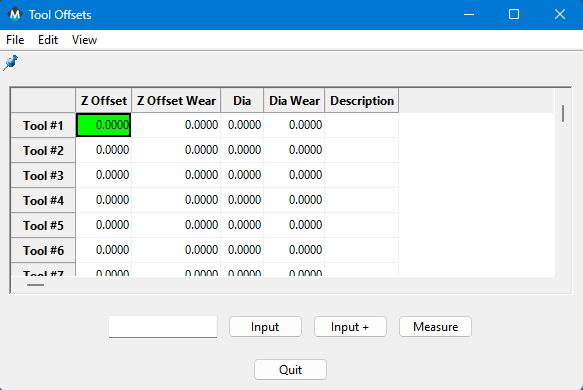
Modify the tool table
Section titled “Modify the tool table”- Open the tool table: View → Tool Tables.
- Open the editor: Edit → Table Fields.
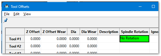
- On the Optional Field tab, add
XOffsetandYOffset(select, then Move Pri), and click OK. - Choose a master tool, measure each other tool’s X/Y distance from it, and enter the offsets.
 12
- 1Testing 1
 1
Tool changer setup
Section titled “Tool changer setup”The MachMotion plugin supports wine-rack and carousel tool changers. Both combine user-defined rack/pocket positions with a pre-programmed change sequence and built-in safety checks. The changer works with the rack parallel to X or Y.
Configure the correct orientation
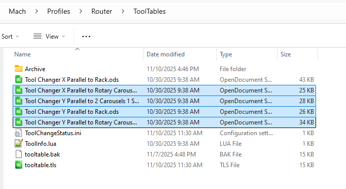
- Determine which axis the rack/carousel is parallel to (X or Y).
- Open
C:\Mach\Profiles\Router\ToolTables. - Keep the file that matches your orientation; archive the others (optional, keeps things clean).
Set tool pocket positions
- Carefully position a tool in each pocket holder.
- Record the machine-coordinate (G53) position for that pocket.
- Enter each recorded value into the corresponding tool-pocket field.
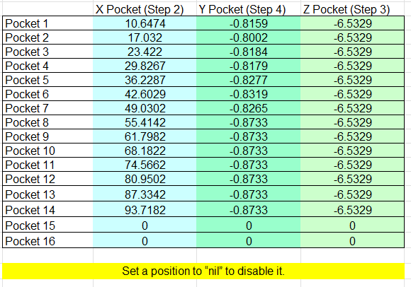
After entering positions you must save the document so the CSV conversion macro runs; otherwise the changed positions have no effect.



Global Monitoring System
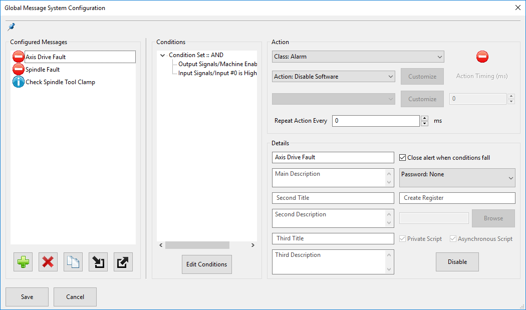
Section titled “Global Monitoring System”The Global Monitoring System sets up user alerts/messages and controls I/O based on conditions. The machine watches for specified conditions and takes action when they are met. Open it via Configuration -> Plugins -> Global Monitoring System.
Monitor classes
The system can initiate four classes of action:
- Alarm — emergency conditions; can disable the machine or stop motion; requires operator intervention.
- Warning — non-critical issues; prevents Cycle Start; alerts the operator.
- Notice — informational only; takes no automatic action.
- Process — background control actions; does not alert or block Cycle Start.
Conditions
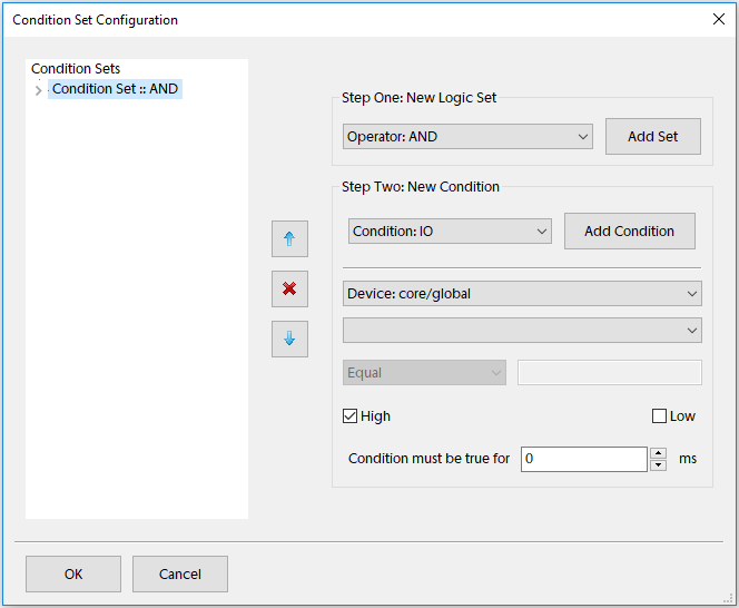
Conditions are organized into sets (AND / OR / NOT) and items. Most monitors only need a single AND set. Add an item by choosing a condition type, filling in the details, and pressing Add Condition.
Auto tool changer manual override
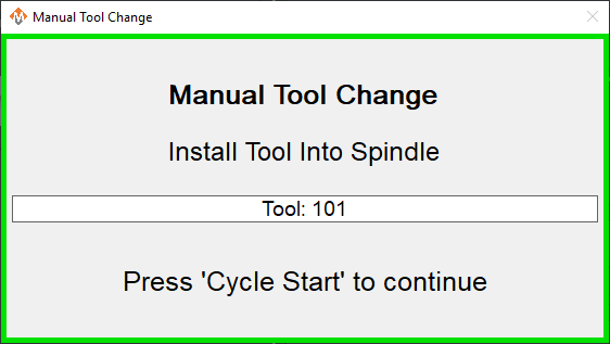
Section titled “Auto tool changer manual override”Used when a tool doesn’t fit the magazine and must be manually loaded/unloaded. Add a
non-pocketed tool range in ToolInfo.lua:
{["Name"] = "Spindle (1) Manual", ["Start"] = 100, ["End"] = 199, ["UseToolPocket"] = 0},Now M6 T100-M6 T199 trigger manual changes.
View and modify MachPro settings
Section titled “View and modify MachPro settings”The reference below is structured data, not a hand-typed table: filter by text, and set your Machine Profile machine type to see only the settings relevant to your machine (e.g. Plasma or Waterjet rows).
| Category | Setting | Constraints | Default | Units | Machine types |
|---|---|---|---|---|---|
| Preferences Backup | Automatic Backup Interval | min:0, max:365 | 10 | Days | all |
| Preferences Dialogs | Enable Confirmation Dialogs | Yes/No | Yes | -- | all |
| Softlimits Startup | Auto Enable SoftLimits | No, Homing, Startup | Homing | -- | all |
| Homing Home All | Home All Button Options | Home Selected Instance, Home All Instances | Home All Instances | -- | all |
| Overrides Feedrate | Feedrate Override Max Percent | min:0, max:300 | 300 | Percent | all |
| Measuring and Offsets Auto Tool Setter | Tool Setter Approach Speed | min:0, max:100000 | 100 | Units/Min | mill, router |
| Spindle Warm Up | Spindle Warm-Up Enabled | -- | No | -- | mill, router, lathe |
| Tool Changer Settings | Tool Change Method | Ignore, Manual, Auto | Manual | -- | mill, router |
| Shape Cutting Plasma | Plasma Error Input | -- | IO$HiCON$P11 Input 1 | -- | plasma |
| Shape Cutting Oxy Fuel | Oxy Fuel Heads | 1,2,3,4 | 4 | -- | plasma |
| Height Controllers Machine Options | Height Controller Device Name | Not Used, SoftHC, RollerHead, ArcPro, NeuronTHC | Not Used | -- | plasma |
| Jet General | Jets Enabled | min:1, max:8 | 1 | -- | waterjet |
| Jet Pump | Jet Pump Off On End Of Program | -- | Yes | -- | waterjet |
| Drill Bank Settings | Drill Bank Number of Drill Banks Enabled | min:0, max:4 | 0 | -- | router |
GCAdapter scripting API
Section titled “GCAdapter scripting API”The GCAdapter rewrites G-code into Mach-compatible G-code. Block functions:
has(passed_word, close_to, thresh) Looks for passed_word in the block; returns true if found. Accepts a full word (X32) or a code (G).
block:has("G53")block:has("M06", "true", .0006)
ModWord(self, old_word, new_word) Replaces old_word with new_word in the current block. Word or code (both must match kind).
block:ModWord("M02","M30")block:ModWord("G43.4","G43")
AddWord(self, new_word) Adds new_word onto the end of the current block.
block:AddWord("M06")
InsertBlockAfter(new_block) Inserts a new block of G-code on the line after the current block.
block:InsertBlockAfter("G00 X2 Y6.77 Z0")
CommentBlock(self, str) Comments out the entire block that exactly matches str (when the match is not already a comment).
block:CommentBlock("M04")
Configure Gantry Alignment
Configure and auto-align a gantry axis, including an Elite-only automatic alignment routine shown only to Elite readers.
A gantry axis drives two motors on one axis of motion. Alignment squares the two sides so the gantry does not rack. Set your Machine Profile to MachElite and pick a release to see how content adapts to your machine and edition.
Configure the master and slave motors
Section titled “Configure the master and slave motors”Assign the master motor and the paired slave motor to the gantry axis, then set the per-motor home offset so both sides reference square.
Automatic alignment
Section titled “Automatic alignment”Automatic gantry alignment measures both home switches and computes the squaring offset for you. This is an Elite feature — it appears for Elite readers and is hidden for Pro.
To align manually, jog each side to its home switch, record the offset, and enter it in the gantry configuration.
This MachPro/MachElite release exposes the gantry configuration under Machine Setup → Axes → Gantry.
On large routers, re-check squareness after the table warms up; thermal growth on long spans can reintroduce a small rack.
Mill and Router Setup Manual
End-to-end mill/router setup - connection, axis setup, homing, spindle, GMS, lube, and tool changers. Migrated from BookStack, edited in the rich CMS editor.
Introduction
Section titled “Introduction”Complete these steps in order. Steps that integrate with a specific motion controller are covered in that controller’s integration documentation.
- Connect the motion controller and MachPro PC with a shielded network cable.
- Connect the cables between the motion controller and the drives.
- MachPro startup and license install.
- Axis setup and calibration.
- Map input signals, then set up homing (and any slave-axis homing).
- Set soft limits, map output signals, and configure the spindle.
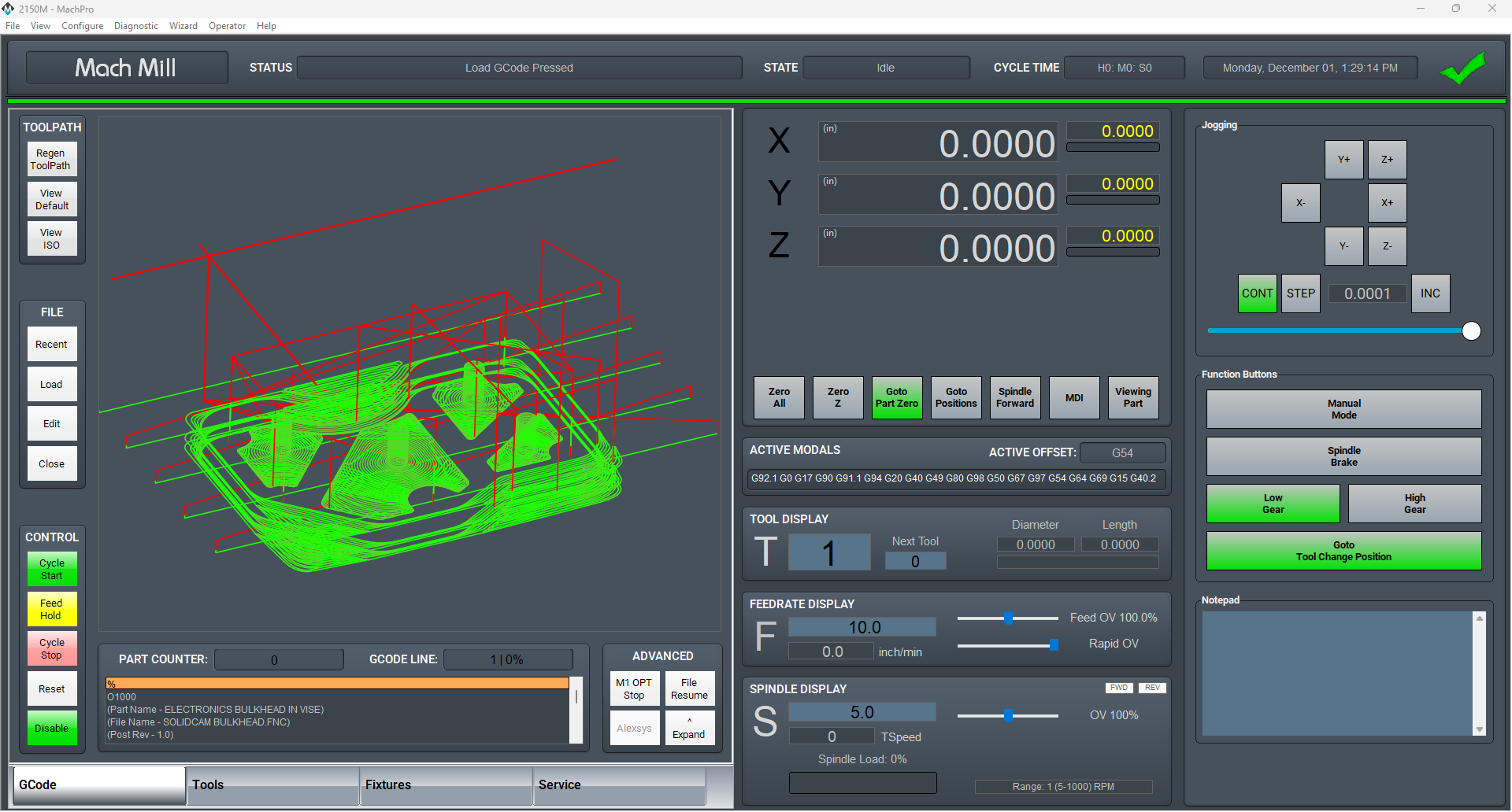 123
- 1Machine status and mode indicators
- 2Position readout (DRO)
- 3Cycle start / feed hold controls
Languages
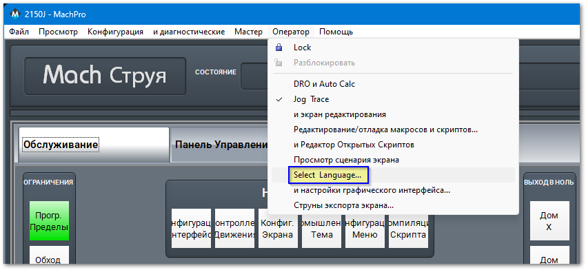
Section titled “Languages”You may change the display language for MachPro screen labels and buttons from Operator → Select Language. Restart MachPro after selecting a new language.
Spindle settings
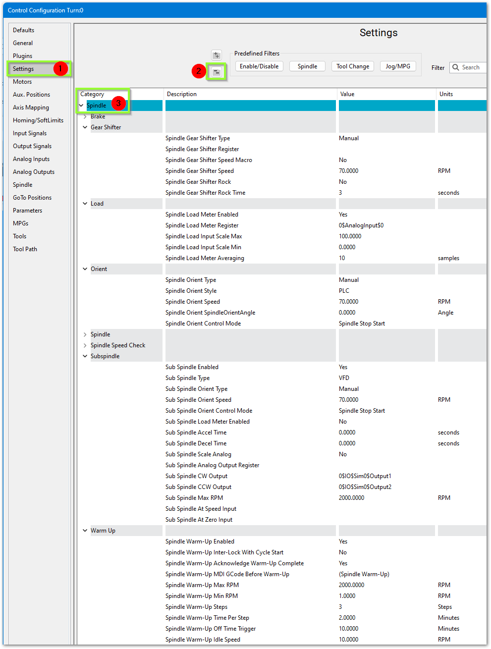
Section titled “Spindle settings”Open Configure → Control → Settings, flatten the tree, and expand the Spindle section. The most common features:
- Gear shifter — configure gear ranges, then set Max RPM per gear (M40-M45).
- Orient — MachPro uses M19; Manual mode works with defaults.
- Sub spindle — set Enabled, CW/CCW outputs, and Max RPM (M13/M104/M105).
Global Monitoring System
Section titled “Global Monitoring System”The Global Monitoring System sets up user alerts/messages and controls I/O based on conditions. The machine watches for specified conditions and takes action when they are met. Open it via Configuration -> Plugins -> Global Monitoring System.
Monitor classes
The system can initiate four classes of action:
- Alarm — emergency conditions; can disable the machine or stop motion; requires operator intervention.
- Warning — non-critical issues; prevents Cycle Start; alerts the operator.
- Notice — informational only; takes no automatic action.
- Process — background control actions; does not alert or block Cycle Start.
Conditions
Conditions are organized into sets (AND / OR / NOT) and items. Most monitors only need a single AND set. Add an item by choosing a condition type, filling in the details, and pressing Add Condition.
Tool changers
Section titled “Tool changers”The MachMotion plugin supports wine-rack and carousel tool changers. Both combine user-defined rack/pocket positions with a pre-programmed change sequence and built-in safety checks. The changer works with the rack parallel to X or Y.
Configure the correct orientation
- Determine which axis the rack/carousel is parallel to (X or Y).
- Open
C:\Mach\Profiles\Router\ToolTables. - Keep the file that matches your orientation; archive the others (optional, keeps things clean).
Set tool pocket positions
- Carefully position a tool in each pocket holder.
- Record the machine-coordinate (G53) position for that pocket.
- Enter each recorded value into the corresponding tool-pocket field.
After entering positions you must save the document so the CSV conversion macro runs; otherwise the changed positions have no effect.
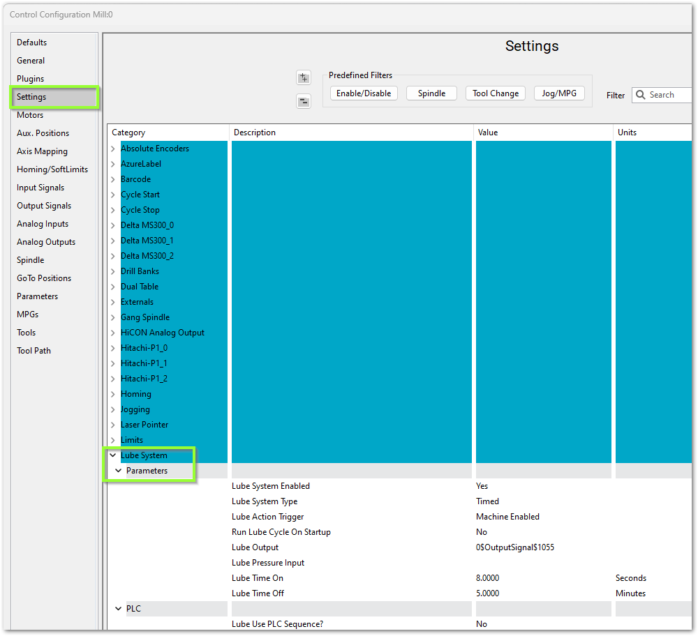
Lube system
Section titled “Lube system”If your system has an oiler, open Configure → Control → Settings and scroll to Lube System. Enable it, choose an action trigger, and set the output, run time, and time between cycles. Start conservative and increase.