Mill and Router Setup Manual
Introduction
Section titled “Introduction”Complete these steps in order. Steps that integrate with a specific motion controller are covered in that controller’s integration documentation.
- Connect the motion controller and MachPro PC with a shielded network cable.
- Connect the cables between the motion controller and the drives.
- MachPro startup and license install.
- Axis setup and calibration.
- Map input signals, then set up homing (and any slave-axis homing).
- Set soft limits, map output signals, and configure the spindle.
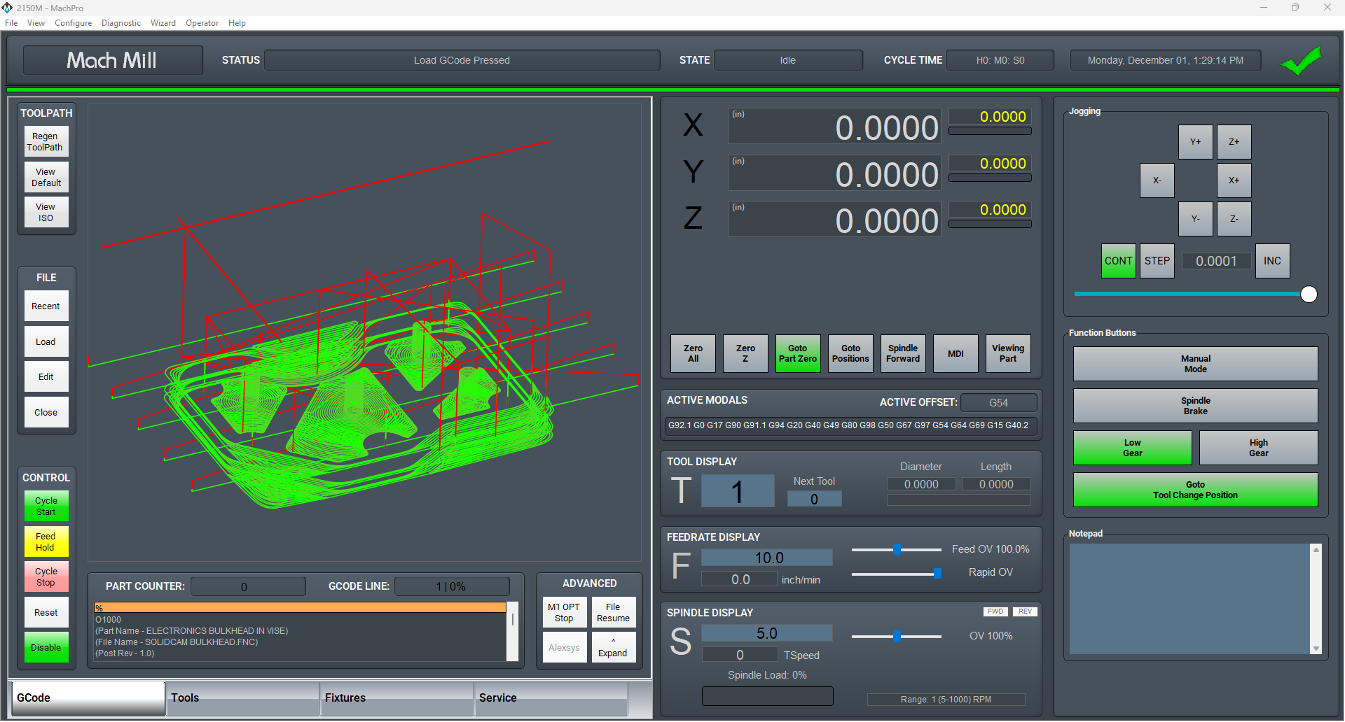 123
- 1Machine status and mode indicators
- 2Position readout (DRO)
- 3Cycle start / feed hold controls
Languages
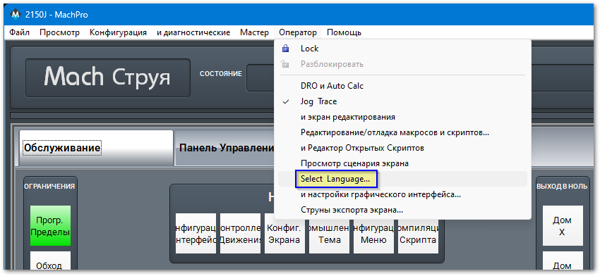
Section titled “Languages”You may change the display language for MachPro screen labels and buttons from Operator → Select Language. Restart MachPro after selecting a new language.
Spindle settings
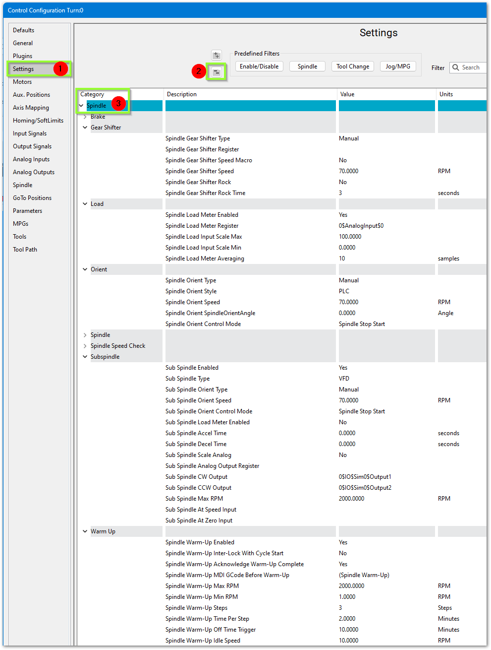
Section titled “Spindle settings”Open Configure → Control → Settings, flatten the tree, and expand the Spindle section. The most common features:
- Gear shifter — configure gear ranges, then set Max RPM per gear (M40-M45).
- Orient — MachPro uses M19; Manual mode works with defaults.
- Sub spindle — set Enabled, CW/CCW outputs, and Max RPM (M13/M104/M105).
Global Monitoring System
Section titled “Global Monitoring System”The Global Monitoring System sets up user alerts/messages and controls I/O based on conditions. The machine watches for specified conditions and takes action when they are met. Open it via Configuration -> Plugins -> Global Monitoring System.
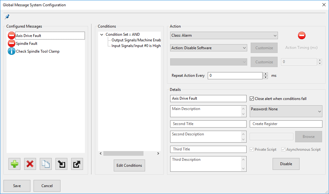
Monitor classes
The system can initiate four classes of action:
- Alarm — emergency conditions; can disable the machine or stop motion; requires operator intervention.
- Warning — non-critical issues; prevents Cycle Start; alerts the operator.
- Notice — informational only; takes no automatic action.
- Process — background control actions; does not alert or block Cycle Start.
Conditions
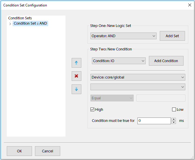
Conditions are organized into sets (AND / OR / NOT) and items. Most monitors only need a single AND set. Add an item by choosing a condition type, filling in the details, and pressing Add Condition.
Tool changers
Section titled “Tool changers”The MachMotion plugin supports wine-rack and carousel tool changers. Both combine user-defined rack/pocket positions with a pre-programmed change sequence and built-in safety checks. The changer works with the rack parallel to X or Y.
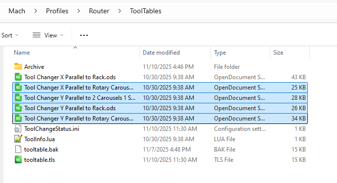
Configure the correct orientation
- Determine which axis the rack/carousel is parallel to (X or Y).
- Open
C:\Mach\Profiles\Router\ToolTables. - Keep the file that matches your orientation; archive the others (optional, keeps things clean).
Set tool pocket positions
- Carefully position a tool in each pocket holder.
- Record the machine-coordinate (G53) position for that pocket.
- Enter each recorded value into the corresponding tool-pocket field.
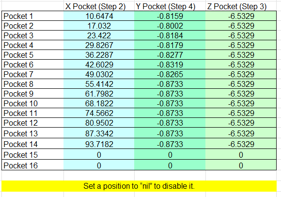
After entering positions you must save the document so the CSV conversion macro runs; otherwise the changed positions have no effect.


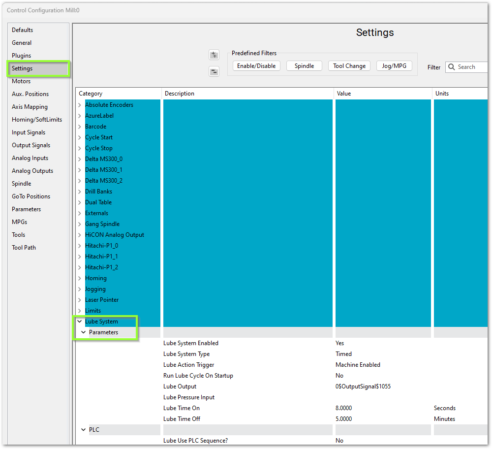
Lube system
Section titled “Lube system”If your system has an oiler, open Configure → Control → Settings and scroll to Lube System. Enable it, choose an action trigger, and set the output, run time, and time between cycles. Start conservative and increase.